
In the modern glass industry, float glass, renowned for its high flatness, large production capacity, and stable quality, holds a dominant position in the glass product market. The core equipment of float glass production – the float glass furnace, often regarded as the "heart" of the entire production line – directly determines the quality of the glass products, production efficiency, and the economic benefits of the enterprise. Currently, large float glass furnaces generally adopt air-fuel combustion and are predominantly regenerative cross-fired furnaces. The regenerator, as a critical component of the float glass furnace, plays an irreplaceable role in the energy utilization and stability of the thermal regime of the furnace.
The refractory materials used in the construction of the regenerator account for approximately 1/3 to 1/2 of the total furnace refractory weight. The checkerwork, being the main structure of the regenerator, works in conjunction with the ports to undertake the crucial functions of supporting combustion in the furnace, supplying energy, and recovering waste heat. To enhance the melting capacity of large furnaces, the industry typically chooses checker bricks with high heat exchange efficiency, such as those with a cylindrical shape. However, during the long-term operation of the furnace, various factors can lead to blockage issues within the regenerator checkerwork. Once the checkerwork becomes blocked, the heat exchange efficiency of the furnace decreases significantly, and in severe cases, can even lead to the collapse of the checkerwork. This not only may force the enterprise to perform hot repairs to replace the checker bricks ahead of schedule but also, if furnace pressure becomes excessive and is not addressed promptly, can cause severe damage to the furnace structure. This situation can lead to a shortened furnace campaign and an premature cold repair, negatively impacting both production stability and cost control. Therefore, in-depth research into the causes of blockage in float glass furnace checkerwork, its maintenance methods, combined with the application of fused cast AZS blocks, is of paramount practical significance for ensuring the stable operation of float glass production, extending furnace service life, and reducing production costs.
1.Overall Structure and Working Principle of Float Glass Furnaces
1.1 Overall Structure of Float Glass Furnaces
A float glass furnace is a large, complex thermal equipment with comprehensive functions, primarily composed of the melting zone, refining zone, cooling zone, regenerators, ports (burners), and flues.
Melting Zone: As the core area of the furnace, its main function is to heat the batch materials to a high temperature until they fuse into molten glass. The bottom, sidewalls, and breast walls of the melting zone are constructed using high-quality refractories that are resistant to high temperatures and corrosion, to withstand temperatures exceeding 1500°C and the erosive action of the molten glass. The furnace bottom in the melting zone is typically equipped with electric heating elements to provide supplementary heat during furnace start-up and operation, ensuring complete melting of the batch materials.
Refining Zone: Located after the melting zone, its purpose is to remove bubbles from the molten glass, thereby improving its clarity. The temperature in the refining zone is slightly lower than in the melting zone, usually controlled around 1400°C. Through proper furnace structure design and control of thermal parameters, bubbles in the molten glass can rise and escape effectively.
Cooling Zone: This section receives the refined molten glass and gradually lowers its temperature to a level suitable for entry into the tin bath (typically 1100–1200°C). The cooling zone employs zonal cooling, controlling the cooling rate to avoid generating internal stresses in the glass due to sudden temperature drops.
Regenerators: As mentioned previously, these are key parts of the furnace for waste heat recovery and preheating combustion air. Each regenerator is associated with a pair of ports and facilitates heat transfer and storage through its checkerwork (grid of bricks). The regenerator shell is usually made of steel plates, lined with refractory bricks internally to minimize heat loss.
Ports (Burners): These connect the regenerators to the melting zone. Their primary function is to inject the preheated combustion air from the regenerators, mixed with fuel, into the melting zone to form a stable flame that provides heat for melting the batch materials. The structural design of the ports directly affects the flame shape, length, and temperature distribution, significantly influencing melting efficiency and energy consumption.
Flues: These are responsible for channeling the combustion exhaust gases from the furnace and directing them into the regenerators for waste heat recovery. Flue design should ensure smooth gas flow with low resistance, while also incorporating effective insulation measures to reduce heat loss.
1.2 Working Principle of Float Glass Furnaces
The float glass furnace is a complex thermal system that transforms raw materials into high-quality flat glass through a series of processes including continuous batch charging, high-temperature melting, regenerative waste heat recovery, float forming on a molten tin bath, and precise annealing and cooling.
Specifically, the melter is responsible for melting the batch materials into homogeneous molten glass at 1600-1700°C. The regenerators significantly enhance thermal efficiency through periodic heat exchange via the checkerwork. The tin bath utilizes molten tin to allow the glass ribbon to spread naturally, forming a smooth, fire-finished surface. The lehr (annealing furnace) then employs precisely controlled temperatures to relieve internal stresses within the glass. The entire process enables continuous and highly efficient glass production. The application of high-performance refractories, such as fused cast AZS blocks, ensures the long-term stable operation of the furnace in the harsh high-temperature and corrosive environment.
2.Characteristics of Fused Cast AZS Blocks and Application in Float Glass Furnaces
2.1 Types and Characteristics of Fused Cast AZS Blocks
Fused cast AZS blocks are high-grade refractories produced by an electric melting process. Based on their chemical composition and performance characteristics, the main types include fused cast alumina-zirconia-silica (AZS) blocks, fused cast mullite bricks, and fused cast alumina bricks.
.png)
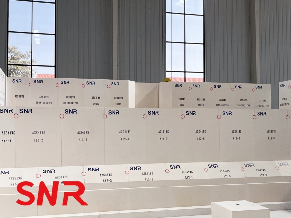
Fused Cast AZS Blocks: Fused zirconium corundum blocks have extremely high high temperature resistance, and their operating temperature can reach above 1600℃, and they can withstand high temperature erosion and erosion of molten glass. Simultaneously, they possess excellent chemical stability and strong resistance to corrosion from various components in the glass melt (such as alkali metal oxides, molten glass, etc.). This effectively resists penetration and erosion by the glass melt, reducing defects in the glass (such as stones, cords, etc.). Furthermore, Fused cast AZS blocks have a dense structure, high bulk density, high mechanical strength, and good thermal shock stability. This allows them to withstand the thermal stresses induced by temperature changes during furnace heat-up, cool-down, and normal operation, minimizing the risk of cracking or spalling.
Fused Cast Mullite Bricks: Produced primarily from alumina and silica raw materials via electric melting, their main mineral phase is mullite (3Al₂O₃·2SiO₂). Fused cast mullite bricks have a high refractoriness (up to 1790°C), good high-temperature strength, and creep resistance, allowing them to maintain good structural stability at high temperatures without deforming easily. They also offer relatively good thermal shock stability and resistance to chemical attack, enabling them to withstand a certain degree of temperature fluctuations and corrosion from chemical media. They are widely used in areas like the cooling zone and flues of glass furnaces.
Fused Cast Alumina Bricks: These are made mainly from high-purity alumina raw materials through electric melting, with alpha-alumina being the primary mineral phase. Fused cast alumina blocks feature very high purity (Al₂O₃ content can exceed 99%), high density, high strength, and excellent high-temperature performance, with a service temperature exceeding 1800°C. They possess outstanding chemical stability, with strong resistance to various chemical media (such as acids, alkalis, salts, etc.). Additionally, they have good thermal conductivity and electrical insulation properties. They are extensively used in critical high-temperature sections of glass furnaces (e.g., melting zone sidewalls, port burner openings) and other high-temperature industrial furnaces.
2.2 Application of Fused Cast AZS Blocks in Float Glass Furnaces
Within a float glass furnace, the working environment and technical requirements vary significantly between different sections. Therefore, the appropriate type of fused cast AZS blocks must be selected based on the specific characteristics of each area.
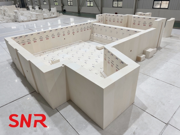
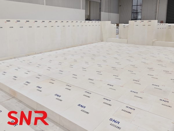
Application of Fused Cast AZS Bricks: Due to their excellent high-temperature resistance and resistance to glass corrosion, fused cast AZS blocks are primarily used in key areas of the float glass furnace such as the melting zone sidewalls, breast walls, port neck, and refining zone sidewalls.
Melting Zone Sidewalls: These are in direct contact with the high-temperature molten glass, enduring its erosive and abrasive action, along with the influence of the furnace atmosphere. Using fused cast AZS blocks for the sidewalls effectively resists this erosion, extends their service life, and reduces defects like stones in the glass. Typically, high-zirconia content AZS blocks (e.g., 41# AZS) are selected for the sidewalls in the hot spot area of the melting zone for enhanced corrosion resistance, while 33# or 36# AZS blocks might be used in other areas to balance cost and performance requirements.
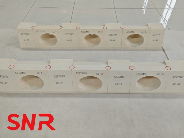
Port Neck: These openings are the channels through which fuel and preheated combustion air mix, burn, and are injected into the melting zone. This area experiences extremely high temperatures, direct flame erosion from hot gases. The use of fused cast AZS blocks to make the port neck can withstand the scouring and erosion of high-temperature flames, ensure the structural stability of the port neck, avoid the influence of flame shape and temperature distribution due to port neck damage, and thus ensure the normal melting process of the melting part.
Refining Zone Sidewalls: Although temperatures here are slightly lower than in the melting zone, the sidewalls still endure glass erosion and some temperature fluctuations. Using fused cast AZS blocks for the refining zone sidewalls ensures structural integrity and chemical stability, preventing impurities from the glass melt from penetrating the refractory, thus guaranteeing good glass quality and reducing defects in the final product.
Application of Fused Cast Mullite Bricks: Fused cast mullite bricks are primarily used in the cooling zone, flues, and certain sections of the regenerators in float glass furnaces.
Cooling Zone: The main function of the cooling zone is to gradually reduce the temperature of the refined molten glass to a level suitable for entry into the tin bath. The temperature in this area is relatively lower (typically 1100–1200°C), but the refractories must withstand slight erosion from the glass melt and thermal stress induced by temperature variations. Fused cast mullite bricks, with their good thermal shock stability and moderate resistance to glass melt corrosion, meet the service requirements of the cooling zone. They ensure the stable operation of this section, preventing issues with glass cooling effectiveness and quality that could arise from refractory degradation.
Flues: The flues are responsible for channeling exhaust gases from the furnace combustion process. These gases are at high temperatures (can exceed 1000°C) and contain certain corrosive components (such as SO₂, CO₂, etc.). Fused mullite bricks have good high temperature resistance and chemical erosion resistance. They can withstand the scouring and corrosion of high temperature exhaust gas in the flue, extend the service life of the flue, ensure the smooth discharge of exhaust gas, and avoid affecting the normal operation of the furnace due to flue blockage or damage.
Application of Fused Cast Alumina Bricks: Due to their very high purity and excellent resistance to high temperatures and chemical attack, fused cast alumina bricks are mainly applied in specific, critical high-temperature areas of the float glass furnace, such as localized high-temperature zones of the melting zone bottom and certain high-temperature components of the ports (burners).In localized high-temperature areas of the melting zone bottom, where temperatures are extremely high and ordinary refractories struggle to perform, the use of fused cast alumina bricks effectively enhances the bottom's ability to withstand intense heat and corrosion, ensuring its structural stability.In certain high-temperature parts of the port (such as the port top and local high-temperature areas of the port side walls), the use of fused corundum bricks can withstand the scouring and erosion of high-temperature flames, extend the service life of the port, and ensure the normal operation of the small furnace.
2.3 Precautions During the Application of Fused Cast AZS Blocks
Quality Control of Masonry Work: The quality of the masonry work for fused cast AZS blocks directly impacts their performance and service life within the furnace. During installation, construction specifications must be strictly followed to ensure uniform and fully filled joints, avoiding issues such as voids or excessively wide gaps. Attention must also be paid to the orientation and arrangement of the bricks. Based on the mechanical stresses and thermal requirements of different furnace sections, the appropriate laying method should be selected to enhance the structural stability and integrity of the lining. Furthermore, the refractory mortar used must be compatible with the fused cast AZS block, possessing good bonding strength and high-temperature resistance to ensure the sealing and monolithic nature of the construction.
Control of Firing and Heat-up Curves: After the furnace lining is completed, a controlled firing and heat-up process is necessary to gradually raise the furnace temperature to its normal operating level. During this phase, the heating rate must be strictly controlled to prevent excessive thermal stress from developing within the fused cast AZS blocks, which could lead to cracking, spalling, or other damage. A rational firing and heat-up schedule should be established according to the material properties of the specific fused cast AZS blocks and the structural characteristics of the furnace. This involves slow, staged temperature increases to ensure the bricks heat uniformly and gradually acclimate to the high-temperature environment. Concurrently, temperature variations across different furnace sections and the condition of the refractories must be closely monitored to promptly identify and address any potential issues.
Routine Maintenance and Care: During normal furnace operation, routine maintenance and care of the fused cast AZS blocks are essential. This includes regular inspections of their condition to promptly identify and address issues such as surface cracks, spalling, or corrosion. Minor damage can often be repaired with suitable patching materials, whereas severely damaged bricks should be replaced promptly to prevent the deterioration from spreading and affecting overall furnace operation. It is also crucial to maintain stable furnace operating parameters, such as temperature and atmosphere, avoiding excessive fluctuations that could subject the refractories to severe thermal shock and damage. Additionally, regular removal of slag buildup, dust, and other deposits from the brick surfaces helps maintain cleanliness, thereby improving their heat dissipation capacity and resistance to corrosion
3.Analysis of Regenerator Checkerwork Blockage Causes
3.1 Structural Damage to Checker Bricks
Checker bricks are the core component of the regenerator checkerwork. Their structural integrity and performance stability directly determine the heat exchange efficiency and service life of the checkerwork. However, during the manufacturing, transportation, construction, firing, and furnace operation stages, various factors can lead to structural damage in the checker bricks, subsequently causing checkerwork blockage.
Defects from the Manufacturing Process: The manufacturing quality of checker bricks is fundamental to ensuring their structural performance. During manufacturing, if the raw material grade is low (containing excessive impurities like iron oxide or calcium oxide) or the raw material ratio is improper, it adversely affects the sintering behavior and structural density of the bricks. Furthermore, factors such as improper sintering temperature control (too low or too high) or insufficient sintering time can result in inadequate sintering, leading to low brick strength and increased porosity. These manufacturing defects make the checker bricks more susceptible to erosion and erosion by high-temperature gases, molten glass flyaways, and other factors during subsequent use, leading to damage such as cracks and spalling, which can pose a risk of grid blockage. For example, if the checker bricks are not strong enough, particles on the brick surface can easily fall off under the long-term erosion of high-temperature airflow. These particles can accumulate in the grid holes, gradually causing them to become clogged.
Damage During Transportation and Construction: During transportation, improper handling, severe vehicle vibration, or inadequate protective measures can cause checker bricks to suffer impact damage. During construction, non-standard practices by workers—such as excessive force during bricklaying, excessive squeezing between bricks, or failure to promptly identify and remove cracked bricks—can generate new cracks or exacerbate existing ones. During furnace heat-up, as temperatures gradually rise, checker bricks undergo thermal expansion. Pre-existing cracks can worsen due to this expansion, leading to structural damage. Damaged bricks alter the gas flow paths within the checkerwork, causing uneven gas distribution. Some flues may become blocked by broken brick pieces, impairing heat exchange efficiency.
Moisture Absorption and Hydration Due to Improper Storage: For basic checker bricks (e.g., magnesia bricks), which are chemically more reactive, exposure to water or prolonged storage in humid environments can lead to moisture absorption and hydration. The main components (e.g., MgO) react with water to form magnesium hydroxide (Mg(OH)₂), causing volume expansion, structural weakening, and reduced strength. When these hydrated bricks are used in the furnace, the magnesium hydroxide decomposes under high temperature, releasing water vapor and leaving behind magnesia. This process creates numerous pores within the brick, further reducing its strength and density. At the same time, the loose structure of the checker bricks is more susceptible to erosion and erosion by high-temperature airflow and flying materials. The particles on the surface of the bricks are more likely to fall off. The fallen particles mix with the flying materials and accumulate in the checker holes, accelerating the process of checker blockage.
3.2 Carryover Deposition
Carryover is a common impurity generated during the operation of a float glass furnace, originating mainly from the entrainment of batch materials during melting and the splashing of molten glass. This carryover enters the regenerator with the high-temperature gas flow and gradually deposits on the surfaces of the checker bricks and within the flues. Long-term accumulation leads to checkerwork blockage.
Causes of Carryover Generation: During the charging of batch materials into the melting zone, factors such as excessive feeder speed, non-uniform batch granulometry (e.g., excessive fines), and significant gas turbulence inside the furnace can cause some batch particles to become entrained by the gas flow, forming carryover. Additionally, in the melting zone, the molten glass, under the erosion and stirring action of the flames, can splash. The resulting small droplets of glass cool and also form carryover. The main components of this carryover are similar to those of the batch and glass melt, containing substantial amounts of SiO₂, Na₂O, CaO, MgO, etc.
Process of Carryover Deposition: As carryover enters the regenerator with the hot exhaust gases, the gas velocity decreases, and the checker bricks act as obstructions. This causes the carryover to gradually settle and deposit on the brick surfaces and within the flues. Deposition occurs more rapidly in cooler regions (e.g., the lower regenerator) because the lower temperature reduces the fluidity of the carryover particles, making them adhere more easily to the brick surfaces. As furnace operation time extends, the deposited carryover increases, gradually blocking the flues, reducing the cross-sectional area for gas flow, increasing flow resistance, and significantly reducing the regenerator's heat exchange efficiency.
Impacts of Carryover Deposition: Carryover deposition not only causes physical blockage and reduces heat exchange efficiency but also inflicts further damage on the checker bricks. Under high temperatures, the deposited carryover can react chemically with the brick surfaces, forming low-melting-point compounds that penetrate the brick structure, degrading its strength and refractory properties. Furthermore, deposition leads to uneven temperature distribution across the brick surfaces, generating localized thermal stresses that can cause cracking and spalling, thereby exacerbating the blockage problem.
4 .Regenerator Checkerwork Maintenance Techniques and Practices
4.1 Daily Monitoring Techniques for Checkerwork
To promptly identify blockage and damage in the regenerator checkerwork and ensure stable furnace operation, a comprehensive daily monitoring system must be established, utilizing various techniques to monitor the operating status of the checkerwork in real-time.
Temperature Monitoring: Temperature is a key parameter reflecting the operating status of the checkerwork. By installing thermocouples at different locations within the regenerator (e.g., top, middle, bottom), temperature variations across different zones can be monitored in real-time. Under normal conditions, the temperature distribution should show a gradual decrease from top to bottom, and be relatively uniform across the same horizontal plane. Abnormal temperature increases or decreases in specific areas, or excessive temperature differences on the same plane, may indicate localized blockage or damage. For example, blockage restricts gas flow, preventing hot exhaust gases from passing through efficiently, leading to temperature rises in the blocked area. Conversely, damaged bricks impede heat transfer, causing temperature drops in those areas.
Pressure Monitoring: Pressure sensors installed at the regenerator inlet/outlet and different heights can monitor pressure changes within the regenerator. Normally, the internal pressure should remain relatively stable, and the pressure differential (between inlet and outlet) should stay within a specific range. An abnormal increase in internal pressure or an increased pressure differential may indicate checkerwork blockage, as blockage increases flow resistance, hindering exhaust gas flow and raising the pressure.
Flue Gas Composition Monitoring: Analyzing the composition of the flue gas at the regenerator outlet provides insights into the combustion conditions and the state of the checkerwork. Abnormally low oxygen content might indicate insufficient combustion air supply, potentially due to inadequate preheating caused by blockage or restricted flow paths. High levels of harmful gases like SO₂ or CO₂ might suggest incomplete fuel combustion or reduced adsorption capacity of the checkerwork due to attack by alkali metal salts.
Visual Inspection: Regularly inspecting the checkerwork through observation ports is also an effective monitoring method. During furnace reversal or shutdown intervals, the surface condition of the checkerwork can be observed to check for brick damage, spalling, carryover deposition, or alkali salt buildup. For large regenerators, industrial borescopes can be used for detailed internal inspection, providing more accurate information about the checkerwork's condition.
4.2 Checkerwork Cleaning Techniques
When monitoring indicates blockage in the regenerator checkerwork, effective cleaning measures must be promptly implemented to remove deposits from the flues and restore heat exchange efficiency. Depending on the severity of blockage and the nature of the deposits, different cleaning techniques can be employed.
High-Pressure Air Blowing: For mild blockage with loose deposits, high-pressure air blowing can be used. This method utilizes high-pressure air (typically 0.6-1.0 MPa) delivered through specialized equipment (e.g., lances) into the checker flues to blast away deposits like carryover and loose alkali salts. During blowing, the air pressure and direction must be controlled to avoid damaging the bricks. To prevent dislodged deposits from settling elsewhere, collection devices should be installed at the regenerator bottom to gather and remove the blown-out material promptly.
Mechanical Cleaning: For severe blockage with hard, consolidated deposits, mechanical cleaning methods are suitable. This involves using specialized mechanical cleaning equipment (e.g., rotary cleaners, impact cleaners). Rotary cleaners use rotating brushes or scrapers to remove deposits from the flues; impact cleaners use hammers to strike and break up deposits on the brick surfaces. When using mechanical methods, the appropriate equipment and parameters must be selected based on the brick material and structure to avoid damage. Dust and debris generated during cleaning must be promptly removed to prevent environmental pollution.
Chemical Cleaning: When blockage is caused by deposits like alkali metal salts that are difficult to remove by physical means, chemical cleaning can be employed. This method uses chemical agents to react with the deposits, dissolving or decomposing them, followed by flushing to remove the products. Common agents include acids (e.g., hydrochloric acid, sulfuric acid) or alkalis (e.g., sodium hydroxide, potassium hydroxide). The choice depends on the deposit composition. For instance, sulfate deposits (e.g., Na₂SO₄) can be treated with hydrochloric acid, reacting to form soluble NaCl and H₂SO₄, which are then flushed away. Carbonate deposits (e.g., Na₂CO₃) can be treated with sulfuric acid, reacting to form soluble Na₂SO₄, CO₂, and H₂O, followed by flushing. Chemical cleaning requires strict control of agent concentration, temperature, and exposure time to avoid corroding the checker bricks. Waste liquid generated must be treated to meet environmental standards before discharge.
Conclusion
From the perspective of the float glass industry's development trajectory, furnace longevity, production efficiency, and green operation and maintenance have become irreversible trends. All of these rely on the technical support of high-performance refractories. The regenerator checkerwork, acting as the "core hub" for the furnace's energy cycle, has its maintenance level and material performance directly determining a company's production efficiency and competitive strength. Fused cast AZS blocks, as key materials in this field, play a vital role in driving technological advancement.
Henan SNR Refractory Co., Ltd (SNR) produces a variety of high-quality refractory materials.If you have any needs, please contact us.