
As the core equipment in glass production, a glass furnace exhibits a complex three-dimensional circulation pattern of molten glass inside the tank, which is influenced by multiple interacting factors. With the rapid development of high-end glass products—such as electronic display glass, photovoltaic glass, and specialty optical glass—higher requirements have been placed on the homogenization and refining quality of molten glass. The stability of the molten glass flow state directly determines whether these requirements can be achieved. In actual production, an unreasonable or unstable flow pattern may result in insufficient batch melting, difficulty in bubble removal, and non-uniform compositional distribution. This not only reduces the product yield and quality but also accelerates the erosion and wear of furnace linings, thereby shortening the service life of the furnace. Therefore, an in-depth study of the main factors affecting the molten glass flow state in glass furnaces, and a clear understanding of the mechanisms by which these factors interact, are of great practical significance for optimizing furnace operation and improving product quality. Based on many years of production experience, this paper provides a comprehensive analysis of the key factors influencing the molten glass flow state and proposes corresponding optimization strategies.
1. Basic Characteristics of Molten Glass Flow in the Glass Furnace
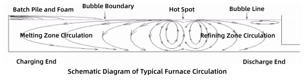
Under the combined influence of thermal driving forces, external forces, and structural constraints, the molten glass inside a glass melting furnace forms a relatively stable circulation system. The typical flow pattern in a furnace can generally be divided into three main modules: circulation in the melting zone, circulation in the refining zone, and flow in the working zone.
The melting zone circulation is mainly driven by temperature differences. After the batch is charged into the furnace from the charging end, it gradually melts under high temperatures. The molten glass formed in the hot spot region rises due to heating and flows back toward the charging end, pushing unmelted batch materials toward the hot spot and completing the melting process. The refining zone circulation is primarily driven by the upward movement of bubbles. Gas bubbles within the molten glass rise under buoyancy, inducing the surrounding molten glass to flow while releasing the gas contained in the bubbles, thereby refining the molten glass. The working zone flow is influenced by factors such as the glass pull rate and stirring devices. It maintains a stable flow velocity to ensure that molten glass enters the forming equipment uniformly.
An ideal flow state should exhibit stable circulation and uniform flow velocity, with clear boundaries between the melting zone and refining zone circulations, and without obvious vortex or stagnant flow regions. The residence time distribution of molten glass inside the furnace should also be reasonable, ensuring that the batch is fully melted and bubbles are completely removed while avoiding excessive erosion of the furnace lining. However, in actual production, fluctuations in various factors may disrupt the stability of the flow pattern, leading to abnormal flow conditions and consequently affecting product quality.
2. Main Factors Affecting the Flow State of Molten Glass in the Glass Furnace
The factors influencing the flow state of molten glass in a glass furnace are complex and diverse. They can generally be categorized into four major groups: temperature field distribution, furnace structural parameters, external interventions, and refractory material performance. These factors are interrelated and interact with each other, collectively determining the final flow state of the molten glass.
2.1 Temperature Field Distribution: The Core Driving Force of Molten Glass Flow
The temperature field distribution is the most fundamental factor determining the flow state of molten glass. The viscosity of molten glass decreases significantly as temperature increases, thereby enhancing its fluidity. At the same time, temperature differences generate thermal convection, which serves as the primary driving force for molten glass circulation. The temperature field distribution in a glass furnace is mainly influenced by the heating method, fuel distribution, and the furnace’s insulation performance. Its uniformity and gradient distribution directly determine the circulation pattern and flow velocity of the molten glass.
2.1.1 Influence of Temperature Gradients
A temperature gradient refers to the temperature difference between different locations within the furnace, including the longitudinal gradient (from the charging end to the discharge end) and the transverse gradient (across the furnace width). The longitudinal temperature gradient is the key factor in forming circulation in the melting and refining zones. A reasonable longitudinal gradient typically shows a distribution where the center is hotter and both ends are cooler, meaning that the hot spot region has the highest temperature, gradually decreasing toward both the charging end and the discharge end. This distribution promotes the formation of a stable double circulation pattern, ensuring that batch melting and bubble refining proceed in an orderly manner.
If the longitudinal gradient is too large, the molten glass flow velocity may become excessive, resulting in insufficient batch melting and inadequate bubble removal. Conversely, if the gradient is too small, the driving force for circulation becomes insufficient, leading to stagnant flow and poor homogenization of the molten glass.
The transverse temperature gradient affects the lateral movement of molten glass. Ideally, the temperature across the furnace width should remain relatively uniform to avoid localized overheating or overcooling. If the transverse gradient is too large, it may induce lateral convection in the molten glass, generating vortices that disrupt the stability of the overall circulation pattern and intensify localized erosion of the furnace sidewalls.
.png)
2.1.2 Influence of Heating Methods and Fuel Distribution
Different heating methods—such as oxy-fuel combustion, air-fuel combustion, electric boosting, and all-electric melting—have significantly different impacts on temperature field distribution.
Oxy-fuel combustion offers advantages such as high combustion efficiency, more uniform temperature distribution, and lower pollutant emissions. These characteristics help reduce temperature gradients and maintain a stable molten glass flow pattern. In contrast, air-fuel combustion involves nitrogen dilution from the air, which lowers flame temperature and often results in less uniform temperature distribution, making the molten glass flow more susceptible to fluctuations.
Fuel distribution directly determines the length, shape, and temperature distribution of the flame. Proper fuel distribution allows the flame to cover the molten glass surface evenly, preventing excessive concentration or dispersion of the flame. If the flame is too long, it may cause excessive temperature at the furnace crown, leading to accelerated erosion of crown refractories and displacement of the hot spot. If the flame is too short, the molten glass may be heated unevenly, increasing temperature gradients and causing flow disturbances.
In addition, the application of electric boosting technology can effectively supplement local furnace temperatures, adjust temperature gradients, and stabilize the molten glass flow state. This approach is particularly suitable for the production of high-end glass products.
2.2 Furnace Structural Parameters: Spatial Constraints on Molten Glass Flow
Furnace structural parameters directly determine the flow space and pathways of molten glass, imposing important constraints on the circulation pattern, flow velocity, and uniformity of the molten glass flow. The main structural factors include the furnace tank configuration, tank depth, weir, and throat or flow channels.
2.2.1 Furnace Tank Configuration and Tank Depth
Glass furnace tank configurations are generally divided into single-tank furnaces and double-tank furnaces (with a dedicated refining tank).
A single-tank furnace has a relatively simple structure, in which the melting zone and refining zone are located within the same tank. The circulation of molten glass is directly influenced by the temperature gradient, making this configuration suitable for small- and medium-scale glass production. A double-tank furnace, on the other hand, separates the melting tank and the refining tank by means of a partition wall. This design effectively prevents unmelted batch materials from entering the refining zone, while allowing independent control of temperature and molten glass flow in each zone. As a result, it significantly improves the refining performance of molten glass and is therefore widely used in the production of high-end glass products.
Tank depth influences the vertical circulation and residence time of molten glass. If the tank is too shallow, the residence time of molten glass becomes insufficient, leading to incomplete batch melting and inadequate bubble removal, while the flow is also more easily affected by external disturbances. Conversely, if the tank is too deep, the resistance to molten glass flow increases, circulation driving forces become insufficient, and stagnant flow zones may appear. In addition, excessive depth increases furnace energy consumption. In practical production, tank depth should be designed according to factors such as glass type and pull rate, and is generally controlled within the range of 1.2–1.8 m.
2.2.2 Weir and Throat
The weir is a barrier structure installed at the bottom of the glass furnace. Its primary function is to separate the melting zone from the refining zone, forcing the molten glass to rise upward. This prevents subsurface flow from entering the refining section while increasing the residence time of the glass melt, thereby improving the refining efficiency. The height and position of the weir directly influence the molten glass flow pattern. If the weir is too high, it increases flow resistance and may accelerate the flow velocity. If it is too low, it cannot effectively separate the circulation loops, which may lead to raw material carry-over into the refining zone.
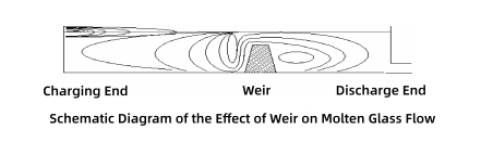
Typically, the weir is installed in front of the hot spot, with a height controlled at about one-third to one-half of the glass bath depth. As shown in the figure, the upward flow of molten glass at the hot spot forces the melt to rise and effectively separates the flow, preventing subsurface currents from entering the refining section. Under the lifting effect of the weir, the molten glass entering the refining zone must rise to the glass surface. This location coincides with the hot spot, and when the weir is well matched with the hot spot, it significantly enhances the glass refining process.
The throat connects the melting tank, refining tank, and working tank, and its size, shape, and position determine the flow path and velocity of the molten glass. If the throat is too narrow, the molten glass flow velocity becomes excessive, which may generate vortices. If it is too wide, the flow velocity becomes too low, leading to stagnant zones and allowing insufficiently refined molten glass to enter the working zone. In addition, the inclination angle of the throat also influences the flow state. A properly designed inclination angle helps ensure smooth molten glass flow and prevents material accumulation.
2.3 External Interventions: Active Control of Molten Glass Flow
External interventions are important measures for actively controlling the flow state of molten glass. They mainly include bubbling devices, stirring devices, and pull rate control, which modify the flow direction and velocity of the molten glass, optimize circulation patterns, and improve flow uniformity.
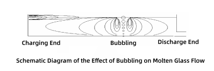
2.3.1 Influence of Bubbling Devices
Bubbling devices consist of one or more rows of pipes inserted from the furnace bottom, distributed along the furnace width. Gas (usually air or oxygen) is introduced under pressure into the molten glass to form bubbles, which rise and eventually burst at the glass surface. These bubbles induce surrounding molten glass to move upward, and adjusting the gas volume can regulate the flow state of the molten glass. Bubbles are ideally released intermittently, with bubble frequency (number of bubbles per minute) used to adjust gas injection. Bubbling is typically positioned along the furnace centerline, about 60% of the furnace length from the charging end.
Initially, bubbles are small (approximately 3–5 mm in diameter) due to lower temperatures and higher pressure at the furnace bottom. As they rise, temperature increases and pressure decreases, causing bubbles to gradually enlarge. The upward driving effect of bubbles is non-uniform, being weaker at the bottom and stronger at the upper layers. Proper placement of bubbling devices creates a single upward flow at the bubble location, which then splits forward and backward, preventing raw batch materials from bypassing the hot spot. When coordinated with the hot spot location, this effect optimizes refining performance.
2.3.2 Stirring Devices and Pull Rate
Stirring devices are mainly used in the working zone. The rotation of stirrers forces molten glass to mix, eliminating compositional and temperature differences, and ensuring uniform flow into forming equipment. Stirring speed must match the pull rate: excessive stirring may generate vortices and introduce bubbles, while insufficient stirring fails to achieve homogenization.
Pull rate is another key external factor influencing flow. If the pull rate is too high, the furnace molten glass level drops, circulation driving forces are reduced, and insufficiently refined molten glass may be quickly discharged, reducing product quality. Conversely, a too-low pull rate results in excessive residence time, over-erosion of the furnace lining, and stagnant flow. In practice, pull rate should be dynamically adjusted based on batch melting speed and refining efficiency to maintain flow stability.
2.4 Fused Cast AZS Block Performance: Indirect Support for Flow Stability
Fused cast AZS blocks in the furnace lining are in direct contact with molten glass. Their material properties and installation quality not only affect furnace campaign life but also indirectly influence flow by impacting temperature field distribution and flow resistance. Fused cast AZS blocks, as a representative high-end refractory, are widely used in critical furnace zones due to excellent high-temperature resistance and corrosion resistance to molten glass, providing important support for stable flow.
2.4.1 Influence of Fused Cast AZS Block Material Selection
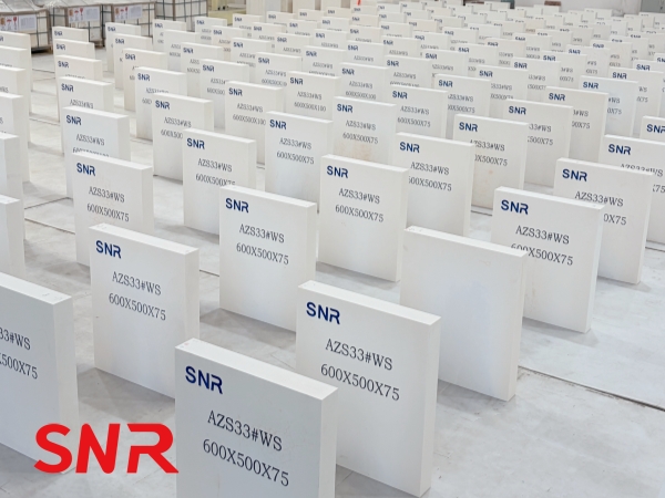
Fused cast AZS blocks are mainly divided into fused zirconia–alumina-silica (AZS) blocks and fused alumina blocks. The AZS series is further classified based on zirconia content: AZS33#, AZS36#, and AZS41#, each suitable for different zones and flow conditions.
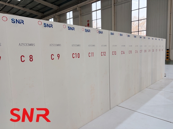
AZS33#: Dense microstructure, good corrosion resistance, low contamination, used in upper melting tank structures, working sidewalls, and paving blocks. Its smooth surface reduces flow resistance and prevents local flow irregularities.
AZS36#: Contains more chain-like zirconia crystals, providing better corrosion resistance than AZS33#, suitable for regions with higher flow velocity or temperature, reducing erosion and maintaining flow direction.
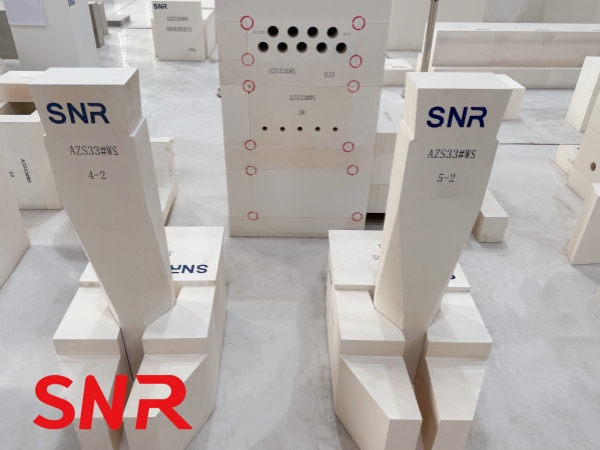
AZS41#: Highest zirconia content, excellent corrosion and high-temperature resistance, used in critical zones such as hot spot walls, weirs, bubbling holes, and throats, preventing brick damage that could disturb circulation.
2.4.2 Influence of Fused Cast AZS Block Installation Quality
The installation precision and quality of fused cast AZS blocks directly affect molten glass flow. Floor bricks should be flat AZS blocks; uneven surfaces create vortices and disturb circulation. Joints between bricks should be strictly controlled within 0.5 mm; larger gaps allow molten glass penetration, causing brick loosening, increased flow resistance, and potential leakage, impacting both safety and flow stability.
In all-electric furnaces, fused cast AZS blocks play an even more critical role. Electric heating makes glass fluidity highly sensitive to temperature distribution; high-temperature-resistant bricks maintain uniform wall temperatures, preventing localized overheating or cooling that would create viscosity differences and disturb flow. Electrode hole blocks must resist corrosion and thermal stress to avoid cracking, leakage, or air-flow disruption, ensuring uniform electric heating and stable flow.
3. Measures to Optimize Molten Glass Flow
Based on the analysis of influencing factors and production experience, the following targeted measures can optimize flow, improve glass homogenization, and enhance product quality:
Optimize temperature field distribution: Use oxy-fuel combustion or electric boosting, reasonably allocate fuel and electric power, adjust flame length and shape, ensure uniform temperature distribution, and control longitudinal and transverse gradients. Regularly check insulation to prevent rapid local heat loss and maintain stable flow.
Optimize furnace structure parameters: Design tank type and depth according to glass type and production scale, adjust weir height and position, and optimize throat dimensions and angles to ensure smooth flow, effective separation, and sufficient residence time.
Properly control external interventions: Optimize bubbling device placement, bubble frequency, and size; dynamically adjust according to flow state. Match stirring speed with pull rate to avoid vortices, stagnant zones, or excessive flow velocity, ensuring uniform flow.
Enhance refractory application: Select fused cast AZS blocks appropriate for each furnace zone, strictly control installation precision, regularly inspect for wear, and promptly replace damaged bricks to prevent flow disturbances.
4. Conclusion
The stability of molten glass flow is critical for ensuring product quality and production efficiency. It is jointly influenced by temperature distribution, furnace structural parameters, external interventions, and fused cast brick performance.
►The temperature field distribution is the core driving force.
►Furnace structure provides spatial constraints.
►External interventions allow active control.
►Fused cast AZS blocks provide indirect support by influencing temperature uniformity and flow resistance.
In practice, optimizing molten glass flow requires careful consideration of glass type, production scale, and actual furnace conditions. By integrating process parameter optimization, structural design, proper fused cast AZS block selection, and strict installation control, molten glass can achieve ideal flow conditions, improving product yield, extending furnace life, and supporting high-quality development of the glass industry.
For further discussion or inquiries, please feel free to contact me: